In other sections of the AutoEZ documentation you will find long (and sometimes long-winded) explanations of how to enter formulas for XYZ coordinates on the Wires sheet, and how to replace straight numeric XYZ values with formulas in existing models, so that various aspects of the model may be controlled via variables. However, for many types of antennas you can create the complete model without directly making a single Wires sheet entry. Here's how.
Stepped Diameter (or Constant Diameter) Yagis
In this example we'll create a
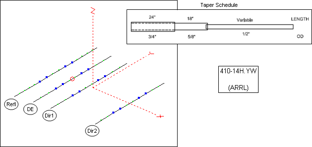
4-element Yagi for the 10M band. This is a modified version of model"410-14H.YW" found in recent editions of The ARRL Antenna Book. Each half-element consists of a 24" section of 0.75" diameter tubing, then an 18" section of 0.625" diameter tubing, then a final section of 0.5" tubing with different lengths for each element. (Lengths are for the exposed portion of each tube. Physical lengths are longer to allow for telescoping overlap.)
On the Wires sheet, use the small Clear All button to delete any existing wires. After that, enter a model title in cell B10. Whatever you enter in cell B10 on the Wires sheet will show up as the "Description title" just above the white area in the EZNEC main window.
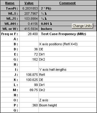
On the Variables sheet, again use the Clear All button to delete any existing variables. If necessary, use the Change Units button to reset the units choice for the new model, inches/inches for this example. Change the frequency (cell C11) as desired, 28.4 MHz for this example.
Then enter initial values and comments for as many new variables as you'll need. With Yagis the usual practice is to put the reflector on the Y axis and not bother using a variable for its X coordinate. Hence we'll need 3 variables for the element positions on the X axis (with the Reflector fixed at X=0), 4 variables to control the Y axis half-lengths, and 1 variable to control the boom height above ground. You need not define the variables in X/Y/Z order, any arrangement that seems logical to you may be used.
Here's what the Variables sheet might look like for this Yagi.
Still on the Variables sheet, click the Stepped Dia button. If there are existing entries in the dialog window you can modify what is currently showing or you can click the Clear All button to start fresh. Then enter the lengths and diameters to define the "taper schedule" for the model. Use as many length/diameter entries as needed and delete any existing entries beyond the tip section.
Hint: You need not click on each field separately in the dialog. Just enter either a section length or diameter then use the Tab key to move to the next field.
In this example the "outside end" Y coordinates are set via a variable so you need not enter the actual length for the 0.5" diameter tip section. You can enter "999" as a dummy length, or you can enter "N/A", or you can enter something more descriptive such as "TIP". Anything other than "0" (zero) or blank will do. Then in the lower part of the dialog enter the variable name that controls the tip Y coordinate. Remember, when a variable name is used in a dialog window the leading "=" sign is optional. (As of maintenance release v2.0.25, if a tip coordinate override is present it is no longer necessary to enter a dummy value for the final section length. You can leave the final length empty.)
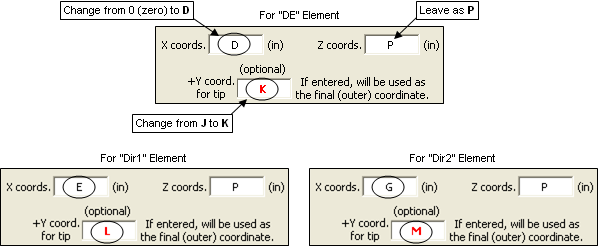
For example, the dialog would have entries like this for the Reflector element.
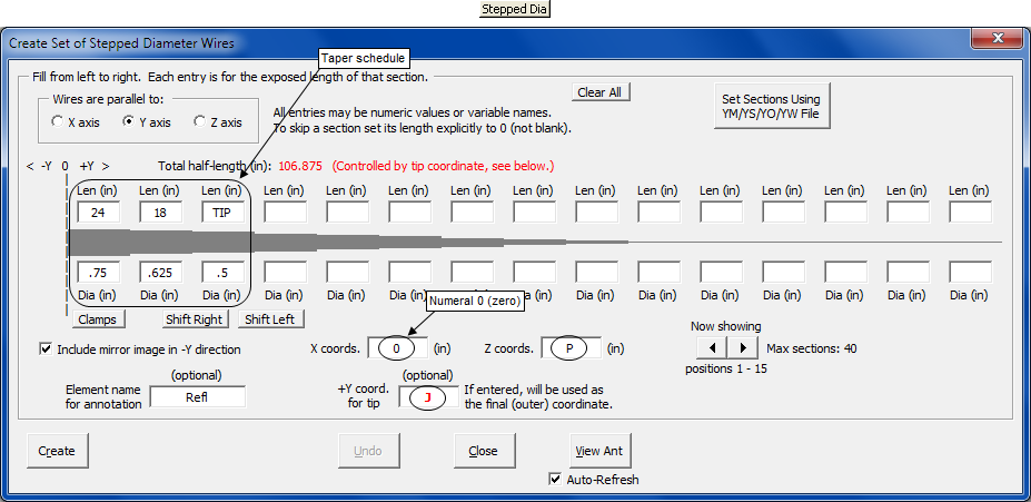
Notice that when you make an entry in the "+Y coord. for tip" field the "Element name for annotation" field is automatically set to whatever comment is associated with that variable. You are free to modify that if you wish.
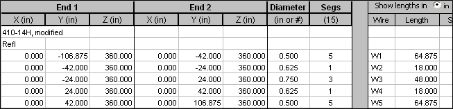
Click Create. All of the wires that make up the Reflector will be added to the Wires sheet, like this.
You can tab back and forth between the Variables and Wires sheets without closing the dialog window, perhaps to verify the creation of wires. You can also make changes on either sheet without closing the window. On the Wires sheet you might want to do that to amend the annotation for a set of wires. On the Variables sheet you can add more variables, change initial values, or amend comments while the window is up. If you tab to a sheet other than Wires or Variables the window will close automatically.
The dialog window will stay up after you click Create so now it's just a matter of changing two fields and creating the DE element, changing the same two fields and creating the Dir1 element, etc.
After the last element is created you can click Close. You're done creating all the wires for the model, 5 for each element, 20 in total, and you didn't have to manually enter anything on the Wires sheet.
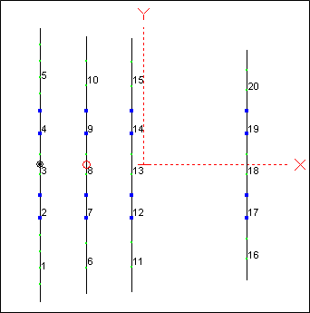
The final step in creating the model is to make sure the source is correctly placed. Tab to the Insr Objs sheet and set the source position to
"Wire 8 / 50%" . Then click the View Ant button to see what you have created. Here's a top-down view.
Now suppose you wanted to create a similar Yagi but with constant diameter tubing. Not necessarily to build, perhaps just for experimentation. You could of course manually enter four wires on the Wires sheet, one for each element. Or you could use the Stepped Dia button again with a "taper schedule" of just a single diameter. For example, to create a Reflector element built from 1.25" (constant diameter) tubing you could make the following entries in the dialog window.
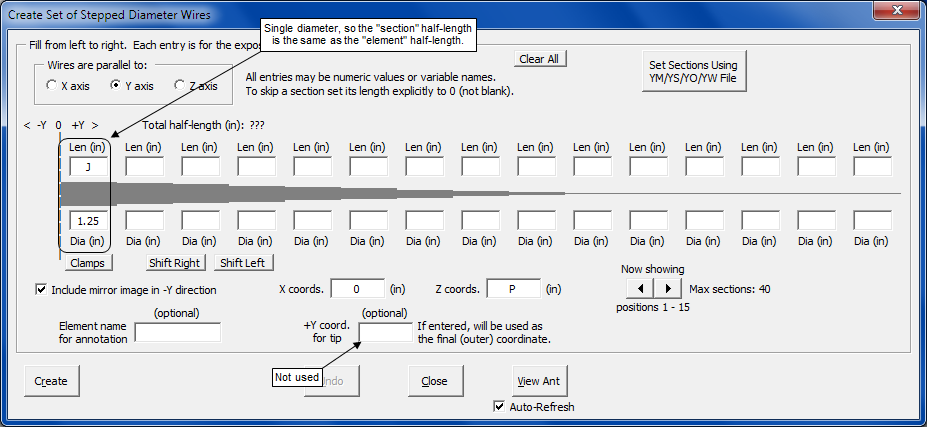
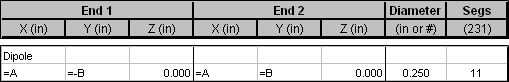
Repeat for the other elements, replacing J in the "Len" field with K, L, or M and replacing "0" (zero) in the "X coords." field with D, E, or G. And if you really don't want to make any entries directly on the Wires sheet you could use the dialog a single time to create a simple dipole with variable length and height, perhaps entering a diameter of "#12" AWG rather than in inches.
Another way to use the dialog is to forego variables all together. You might want to do that if you just want to duplicate a Yagi using dimensions from a publication or web site. In that case you may wish to use the Stepped Dia button on the Wires sheet since no variables will be involved.
Here is what The ARRL Antenna Book shows for the Yagi used in the initial example.
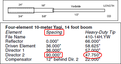
And here is how you could set up the dialog to create the wires for the "Director 2" element.
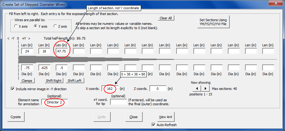
Be careful: Notice that the publication shows spacing between elements as opposed to the position on an axis. You can convert that to an X coordinate value and enter that value ("162" for this example) in the dialog field. Or you could enter the string "36+36+90" (without the quotes) in the field and let Excel do the math for you. Any place where a variable name can be entered you can also enter simple arithmetic expressions.
Finally, for advanced users, you may wish to incorporate the effect of mounting clamps or brackets into your model. AutoEZ has a separate dialog that will do the "equivalent diameter" calculations for you, based on the algorithm described in Sec 9.1 of Physical Design of Yagi Antennas by David B. Leeson, W6NL
(ex-W6QHS) . Click the Clamps button located under the first "Dia" field.
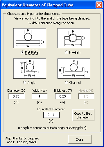
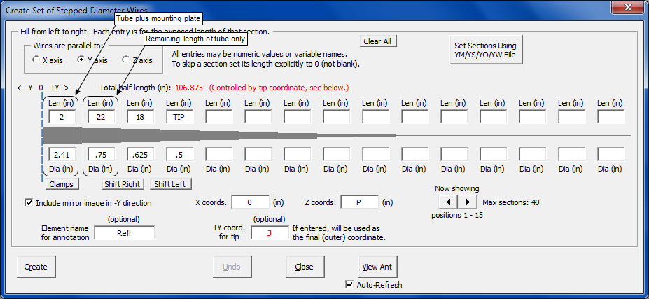
If a 0.75" diameter tube is clamped to a flat plate with width (along the boom) of 4" and thickness 0.25", the equivalent diameter for that portion of the tube in contact with the plate is 2.41". Hence if the plate is also 4" across the boom, or half-length of 2", you would define the Reflector of the initial example like this, where the length of the first section (the equivalent diameter section) is 2" and the length of the 0.75" section has been reduced by the same amount, 2", from 24" to 22".
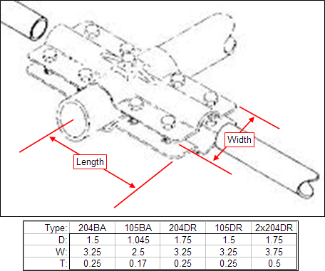
It is easy to confuse the meanings of Width (distance from edge to edge of the clamp, parallel to the boom) and Length (distance from the boom centerline to the edge of the clamp, perpendicular to the boom). The following diagram illustrates the difference and gives the Diameter (D), Width (W), and Thickness (T) for various
Hy-Gain clamps.
If the driven element is to be split and insulated from the mounting plate, as might be done with a hairpin match, you need not recreate the entire taper schedule when defining that element. Just enter "0" (zero) as the length of the first section and increase the length of the second section back to 24". And technically the equivalent diameter of the portion of the split element that is "close to" but insulated from a conductive mounting plate would be more than the tube diameter itself but less than the calculated value for a tube in direct contact with a conductive plate. I am unaware of any algorithm to calculate an equivalent diameter in that case.
Caution: If you simulate mounting plates or brackets you will have a "short and fat" wire at the center of the element. If a source is to be placed on such a wire be sure to increase the segmentation density such that the wire has at least 3 segments. Also, be sure to do an Average Gain Test on the model to insure that the NEC engine is producing reliable results.
For details on how to add a hairpin to your models see Element Lengths - Element Spacing - Hairpin Match with 20M5ELYA.ez on the "Using the Optimizer" page.
Quads and Other Loops
In this example we'll build a 2-element, 5-band quad, as described in recent editions of The ARRL Antenna Book under the heading "A Two-Element, 8-Foot Boom Pentaband Quad". This is a view of what we are shooting for, 40 wires in total.
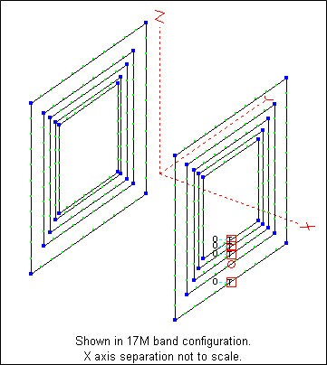
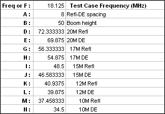
As with the previous example, start by clearing all existing wires and entering a model title in cell B10 on the Wires sheet, clearing all existing variables and changing the frequency (18.125 MHz for this example) on the Variables sheet, and changing the model units if necessary (feet/inches for this model). Then define all necessary variables, perhaps like this, where the initial values for variables D through N represent the circumference of each loop in feet. (Other ways to specify the size of a loop, not used in this example, are to set the length of each side or the diameter of the circumcircle).
The two spiders of the quad are separated by distance A, initially set at 8 ft. Similar to what was done with the previous Yagi example, you could define all the reflector loops to be in the YZ plane at X=0 and all the driven element loops to be at X position A. But suppose for some reason you wanted the mid-point of the boom to be at X=0 with each spider equidistant from there.
You can use arithmetic operators any place where a variable can be entered. So you could define all the reflector loops to have an X axis position of
"-A/2" and all the driven element loops to have an X axis position of "A/2". Click the Loop button and create the loops like this.
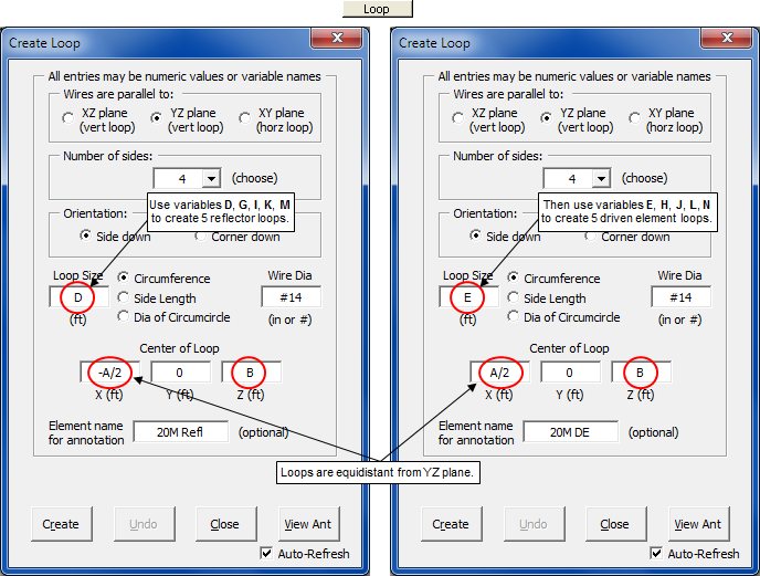
Of course this is only one way to do things. You could instead define the 20M Reflector followed by the 20M DE but then you'd have to keep changing the "Center of Loop" X coordinate for each new loop. You may be willing to do that in order to keep both loops for each band "next to" each other on the Wires sheet.
When you enter a variable name for a loop size the "Element name for annotation" field will be set to whatever comment is associated with that variable. You can amend the field prior to creating the loop or change it later on the Wires sheet. If you enter a numeric value for a loop size the "Element name" field will not be changed, staying either empty or as you last set it.
You can tab back and forth between the Wires and Variables sheets without closing the "Create Loop" window. You can also make changes on either sheet, such as amending wire set annotations or variable values/comments, while the window is up. If you tab to a sheet other than Wires or Variables the window will close automatically.
This model has five different sources, one for each band, each on a different wire. For details on how you can automatically switch the source from one wire to another see Auto-Switched Sources/Stubs with a Multi-Feedpoint Pentaband Quad. Note that in that example the wires were created in a different order so the wire numbers for the five sources will be different.
Aside: In that linked reference you'll also find these words: "... it's straightforward to create the formulas for the XYZ coordinates." That may be true, but not nearly as easy as using the Loop button.
Radials and Verticals
The next example of creating wires will use the Radials button. Since there is nothing particularly complicated about that this example will also show a few ways to use the Resonate button on the Calculate sheet.
The task will be to build a model for a simple 40M vertical with elevated radials. The base of the vertical and the outer ends of the 4 radials will be supported via wooden posts 8 ft tall.
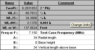
As before, clear all existing wires, clear all existing variables, and change the frequency, 7.150 MHz for this example. Then define three variables as follows, setting the initial lengths for the radials and vertical wire to roughly λ/4 to start.
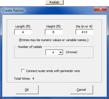
Click the Radials button and fill the dialog fields. Click OK.
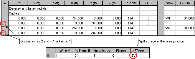
Now let's "tune" the radials to be resonant at 7.150 MHz. On the Wires sheet, temporarily "mark out" wires 2 and 4. Then on the Insr Objs sheet place a split source at
"Wire 1 / 0%". Essentially you a making a dipole out of two opposite radials.
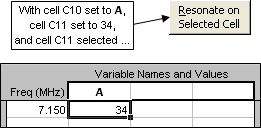
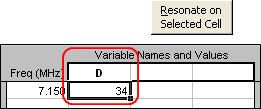
Now tab to the Calculate sheet. Make sure the ground type is "High Accuracy" and the plot type is "Elevation at 0° azimuth". Clear any existing calculation results, set the frequency to 7.150 MHz, enter A as the variable name and "34" as the initial value. Click the Resonate button.
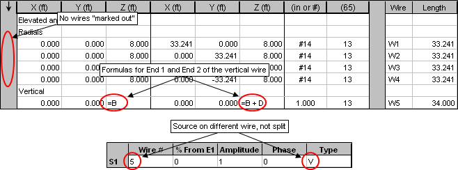
The length of the two halves of the "dipole" will be reset to roughly 33.24 ft. Back on the Wires sheet, "unmark" the other two radials and add an additional wire for the vertical section, using variables B and D as shown and with a nominal diameter such as 1". In addition, use the AutoSeg button to change the segmentation density from the original 20 segments per WL to 50 segments per WL, for reasons that will become clear in a moment.
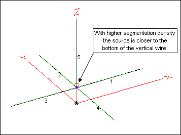
On the Insr Objs sheet change the source to the bottom of the vertical wire.
Had you not changed the segmentation the vertical wire would have 5 segments. You want the source at the bottom of that wire but the closest that EZNEC would be able to place it would be in the middle of the first segment, and since each segment would be 20% of the total length that would be 10% up from the bottom. With a higher segmentation density each segment will be shorter, so the middle of the first segment is much closer to the bottom.
Now let's resonate the vertical wire, this time adjusting variable D instead of A.
The length of the vertical wire will be reset to roughly 34.67 ft. Note that the vertical got longer to achieve resonance while the radials got shorter.
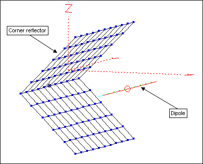
Wire Grids - Corner Reflector
Wire grids are used to simulate flat, solid, conductive surfaces. Typical applications are to model the roof of a vehicle or the roof of a building but in this example we'll construct a corner reflector for the 2M band.
As you work through this example you may wish to save the model after each step. AutoEZ does not have a general purpose "undo" function. If you make a mistake it is much easier to just open the most recently saved model rather than try to reverse your steps.
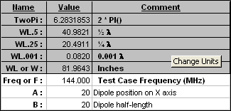
Clear all wires, clear all variables, set the frequency to 144 MHz, and set the units to inches/inches. To simplify the example we'll build the model in Free Space so on the Calculate sheet set that as the ground type. Define two variables as follows although they won't be used until the last step.
The grid will be build as two separate pieces, each measuring 40" along the Y axis and 20" in the "other" direction. Because this is a relatively small grid we can afford (segment count wise) to use double-density spacing for the wires, WL/20 instead of the normal WL/10. (For more information on spacing enter "Wire Grid Creation" on the Index tab of the EZNEC Help.)
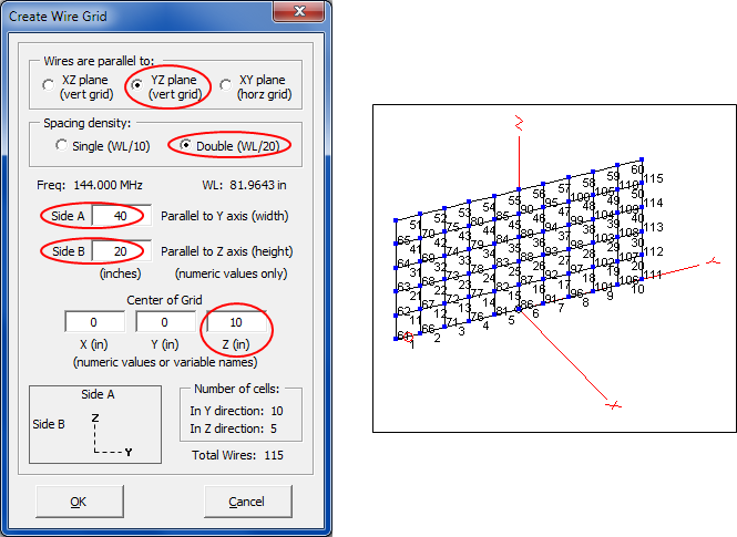
No variables will be used for the grid pieces so tab to the Wires sheet and click the Wire Grid button. Create the first piece using the dialog field values as shown below. Note that this piece is 20" high and the center has been moved up by 10" on the Z axis. That puts the bottom of the grid directly on the Y axis.
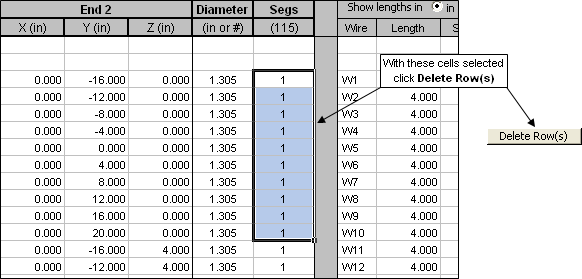
The next step is to delete the wires along the bottom of this piece, wires
1-10 . To delete a row or rows on the Wires sheet you can select cells in any column. In this case it makes sense to select cells in the "Segs" column since that is next to the wire numbers that you want to delete.
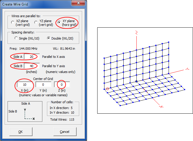
Now build the second piece of the grid. Be careful to note that this piece is built in a different plane and that the 40" Y axis dimension is now Side B, not Side A. Also note that this piece is moved "out" along the X axis by 10" which makes it join perfectly where the wires were deleted in the previous step.
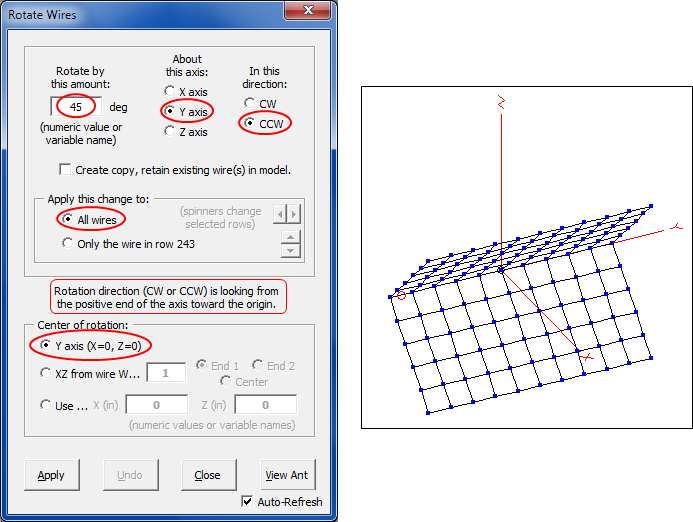
Use the Rotate button to rotate all wires built so far by 45° in a CCW direction about the Y axis.
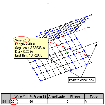
Finally, add a wire for the dipole as the last wire in the model, using variables A and B. Make the diameter a nominal 0.25" and give the wire 11 segments.
Now where to put the source? What's the wire number of the dipole wire? You could click the Add More Info-Only Rows but it's probably easier to just click View Ant, re-orient the view until you can pick out the dipole from the mass of other wires, and point to it with the mouse. Then set the source wire on the Insr Objs sheet.
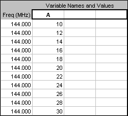
Now you can experiment with adjusting the position of the dipole along the X axis. You might set up a "variable sweep" like this.
Calculate, then tab to the Custom sheet and plot "Slice Max Gain" vs "Variable 1".
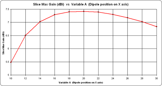
Looks like the initial guess of 20" out from the corner was pretty good.