Examples of using AutoEZ have been created from time to time to address questions raised on various forums and reflectors. This is a collection of such examples, in some cases slightly edited. Step by step instructions are omitted to maintain brevity.
Modeling "Bent Dipole" (and Conventional) 4-Squares, with Feed Systems
Probably most 4-square arrays are constructed using λ/4 vertical elements. Although the elements of the actual antenna are straightforward you must also build the radial field consisting of dozens of intersecting and bonded on-ground or buried wires.
If you have a tower or tall tree available you can build the elements in the form of "bent" vertical dipoles with the tower (or tree) acting as a support structure.
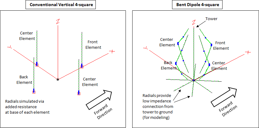
For modeling, the radials for conventional vertical elements are normally simulated by connecting the elements directly to MiniNEC-type ground and then adding a resistance at the base of each element to account for ground loss. But since bent dipole elements will typically have wires with horizontal components within 0.2 wavelengths of ground, use of MiniNEC-type ground would result in inaccurate results. Hence it is necessary to use "High Accuracy" ground and add very-low radials (or buried radials if a NEC-4 engine is being used) in order to simulate a grounded tower. The modeled radial field need not be extensive in this case; there is almost no difference between using 4 or 32 radials. For more information on this subject see "Connecting to High Accuracy Ground" in the EZNEC Help.
Several models have been developed (see zip file at the end of this section) to address both the geometry of the elements as well as the feed system for the array. Conventional (vertical) element array models are also available with the same feed systems which can be used independently or for comparison with the bent dipole arrays. For the array feed system you can choose between "Hybrid Coupler" (with optional phase compensation shunts across port 2 and/or port 3 of the coupler) or "Lahlum/Lewallen" phase shift networks for more complete control over the pattern but with a smaller operational bandwidth.
Wire Geometry:
Here is a portion of the Variables sheet tab for the bent dipole models.
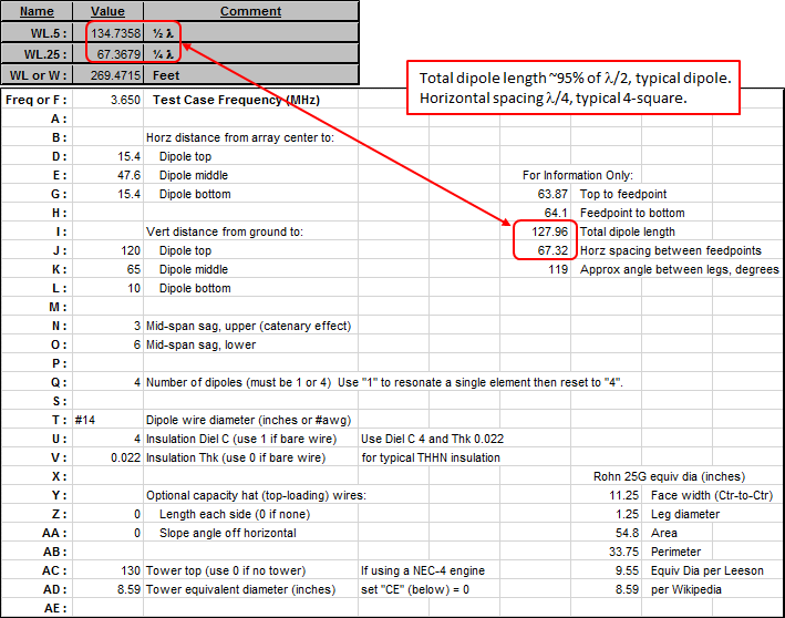
All aspects of the array are controlled by changing the variables. There is no need to make any changes at all on the Wires tab. By changing variables D through AD you can control all the wires of all four dipoles.
The "For Information Only" cells will change automatically as you reset the various variable values. In this example note that the total dipole length (127.96 ft) is about 95% of λ/2 (~134.7 ft) at the array design frequency of 3.650 MHz, as expected, and the horizontal spacing between the dipole feedpoints (67.32 ft) is almost exactly λ/4 (~67.4 ft) as is typical for a
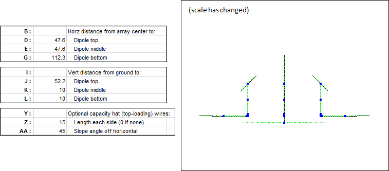
4-square .With the variables set as shown above here is a side view of the wires. Hint: If you resize and reposition the AutoEZ window and the EZNEC "View Antenna" window such that you can see both at the same time, and if you enable the AutoEZ "Auto-Refresh" option next to the View Ant button, you can see the geometry of the wires change as you make changes to the variables.
Another hint: For geometry like this where horizontal offsets D and G are the same, if you wish to adjust the total length while keeping the two halves about equal set variable K using the formula "=(J+L)/2" then adjust variable J (only) as desired.
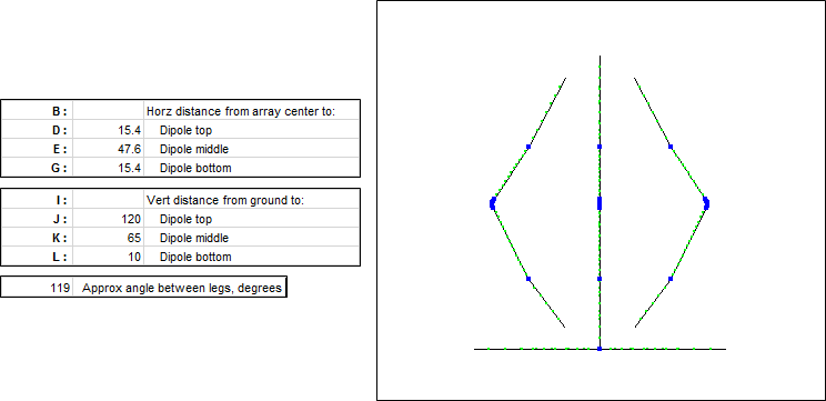
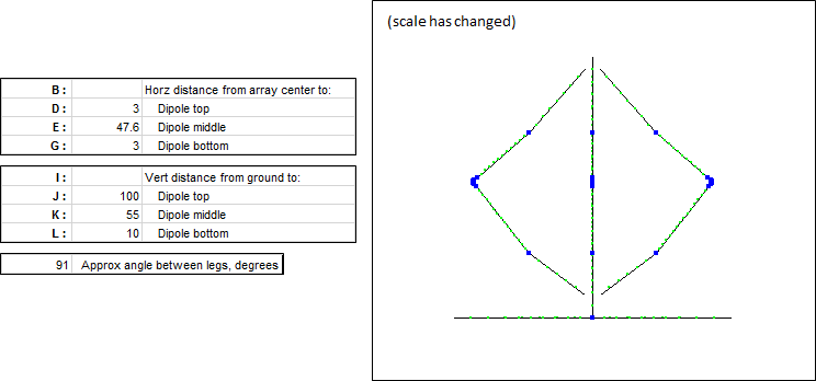
Generally you should try to make the angle between the dipole legs as large as possible. That will result in a broader bandwidth for both SWR and pattern. Opening up the angle also improves the elevation pattern by reducing the high angle response, lowering the take-off angle, and increasing the gain. However, if the tower or other support is not tall enough you may need to reduce the angle as shown in this next example.
Next is an example of changing the variables such that the dipole is in the shape of an "L" and includes sloping top-loading wires. Variable G was set such that the length of the horizontal arm was ~λ/4 and variables Z and AA were set to include 15 ft top-loading wires sloping at a 45° angle. Then Q was set to "1" (single element) and the Resonate button on the Calculate sheet was used to adjust J for resonance. As J is changed the XYZ coordinates of the top-loading wires will automatically adjust to maintain the 45° slope and to meet at the top end of the dipole wire.
After using the Resonate button don't forget to change Q back to "4".
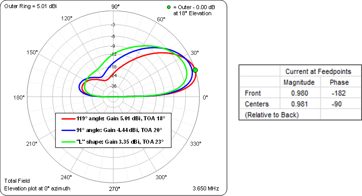
Here is a comparison of the elevation patterns for the three examples above. In all cases the elements were fed in (approximate) quadrature with the magnitude of the current at the dipole feedpoints (approximately) equal. The small difference from perfect quadrature is due to the loss in the λ/4 transmission lines.
Hybrid Coupler Feed System:
After the initial geometry has been established it's time to think about how the elements will be fed. For the "Hybrid Coupler" models variable AZ acts as a "master switch" to configure the feed system. When AZ = False the feed system looks like this.
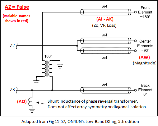
The elements are fed via points Z2 (to the centers) and Z3 (to the back and front). The impedance (R/X) values at Z2 and Z3 are used later for various calculations.
With a hybrid coupler feed system you don't have complete control over the magnitude and phase of the currents at the element feedpoints. The center elements are always (approximately) -90° compared to the back and the front is always (approximately) -180°.
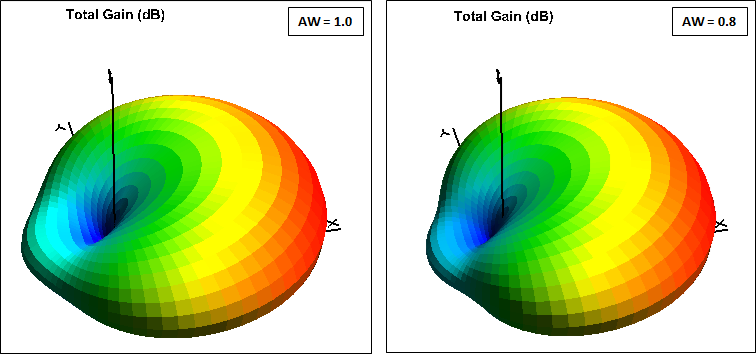
You can adjust the magnitude of the center elements in relation to the back element using variable AW. That affects the back lobe by a small amount.
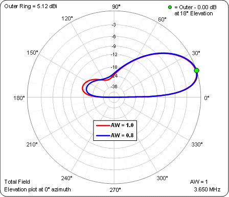
However, to change the center-to-back magnitude ratio in the actual antenna means that you have to be willing to construct your own hybrid coupler, or at least be willing to modify the coupler in a commercial control unit. See ON4UN's
Low-Band DXing 5th edition, chapter 11, sections 3.4.6.1 through 3.4.6.3. Also, it's important to not get caught up in improving only the exact Front/Back azimuth or elevation pattern. It's much more enlightening to look at the full 3D pattern which shows not much difference.
You can also change the characteristics (Zo, VF, Loss) of the transmission lines, variables
AI-AK . Hint: AutoEZ has a built-in database of approximately 100 different line types. You can make use of that database as follows:Select any cell in the (unused) last row of the Transmission Lines table then click the Set Zo, VF, and Loss for Selected Row(s) button.

In the dialog window choose a line type and click OK.
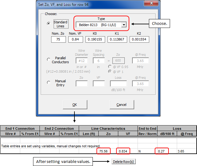
Use the values shown to set variables
AI-AK . AutoEZ makes detailed calculations to account for the fact that Zo and VF change as the frequency changes, as well as the expected change in loss (dB/100 ft). However, there is no need to go overboard with the number of digits when setting the variable values. Click the Delete Row(s) button to remove the table entries as the last step.When "master switch" AZ = True the feed system looks like this.
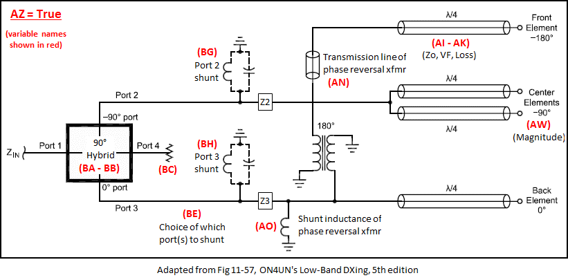
The model will use the impedance values at Z2 and Z3, which were determined with AZ = False (and without the transmission line of the phase reversal transformer), to calculate and suggest values for variables BA, BG, and BH (see below). The suggestions for BG and BH will change as you change your choice for BE. Some choices for BE may require unreasonable component values. Keep in mind these are shunt (parallel) components so values of several thousand ohms (positive or negative) can be replaced with "no shunt". A shunt value of "0" (zero) actually means "open circuit".
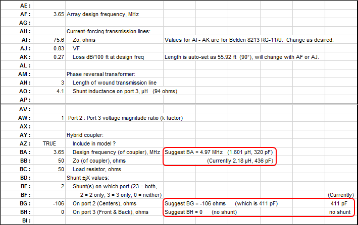
There is a complex relationship between the three suggested settings (coupler design frequency BA and port shunt values BG and BH) and the impedance (R/X) values at Z2/Z3 as were calculated with AZ = False. In turn, the Z2/Z3 impedance values are dependent on the characteristics of the λ/4 (or possible 3λ/4) transmission lines and the shunt inductance of the phase reversal transformer. (Inductance values of 4.1 to 4.8 µH are typical for 80m commercial units.) Details of the calculations are shown below, extracted from the bottom of the scratch pad area on the Variables tab of the models. The Z2/Z3 impedance values used as input to the calculations and the output Port2/Port3 shunt impedance values are rounded to 3 significant digits rather than an arbitrary number of decimal places.
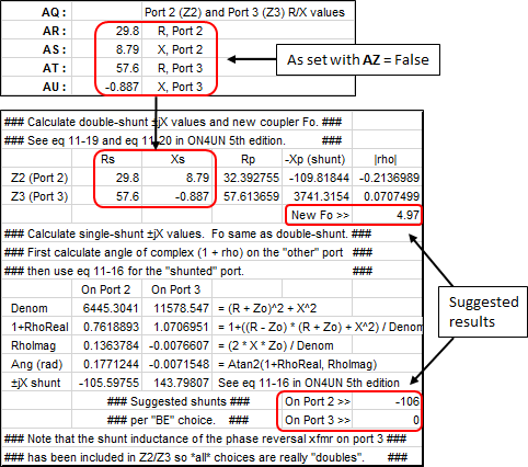
Changing BA is a way to adjust the center-to-back magnitude ratio but again that means that you must be willing to build your own coupler or modify the coupler in a commercial control unit. Changing or not changing BA would result in these two sets of ratios at the element feedpoints, assuming the 411 pF shunt was added across port 2 as shown above. As before, for this particular model the difference has only a minor effect on the pattern.

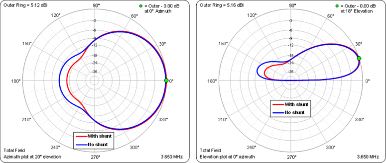
Here is a comparison of azimuth and elevation patterns for the model fed with a hybrid coupler with and without the 411 pF port 2 shunt. The coupler design frequency was left as 3.65 MHz.
After you have completed adjustments to the model at the desired design frequency you'll next want to run some frequency sweeps. On the charts below, the unshaded region spans
3.5 to 3.8 MHZ while the two outer shaded regions show trends for 100 kHz on either side of that range. (Hint: Shading can be added using the AutoEZ Show Band Markers feature on the Custom tab. In this case "bands"3.4 to 3.5 MHz and3.8 to 3.9 MHz were added.)
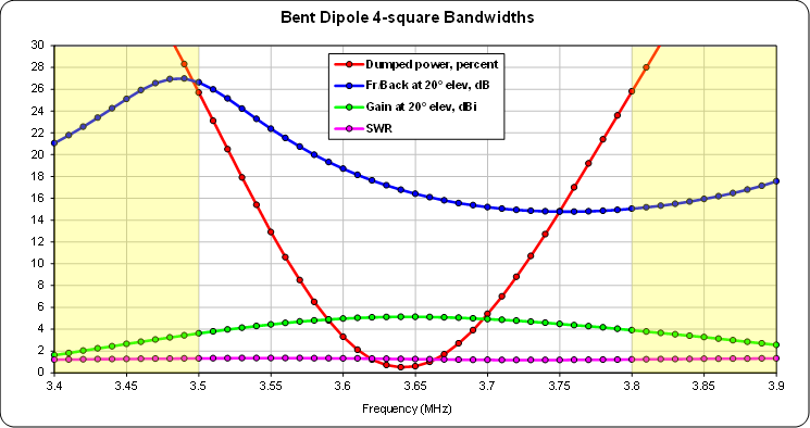
The Front/Back curve can be shifted up in frequency by increasing the value of the port 2 shunt capacitor (smaller
-jX reactance), and vice versa. However, making that change also has a minor effect on the centering of the dumped power curve. That curve can be shifted up in frequency by increasing the resonant frequency of the elements (shorter elements), and vice versa.Here's the frequency sweep after changing the port 2 shunt from 411 pF
(-106 ohms at the array design frequency of 3.65 MHz) to 1038 pF(-42 ohms), which shifted the Front/Back curve up as desired but also shifted the dumped power curve down slightly, and then changing the resonant frequency of the elements from 3.65 MHz (dipole length 127.96 ft) to 3.70 MHz (dipole length 126.35 ft) in order to re-center the dumped power curve.
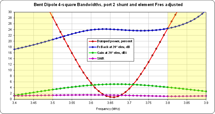
The bandwidth of the dumped power curve can be broadened by changing the design Zo of the coupler, again if you are willing to build your own coupler or modify the coupler in a commercial control unit. But there is an easier way.
The amount of dumped power is related to the impedance values that are presented to ports 2 and 3 of the coupler. Those impedance values can be changed by using transmission lines with a different characteristic impedance. Here are the results when the port 2 shunt is 597 pF (-73 ohms), the resonant frequency of the elements is 3.67 MHz (dipole length 127.25 ft), and
RG-62 (Zo ~92 ohms at 3.65 MHz) is used for the transmission lines.
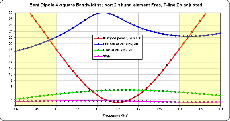
In this case I chose the port 2 shunt value such that the Front/Back would be the same at 3.5 and 3.8 MHz rather than centering the peak of the Front/Back curve.
Lahlum/Lewallen Feed System:
That concludes the discussion of the hybrid coupler feed system. A second way to feed the array is to use "Lahlum/Lewallen" phase shift networks. Models for that also have a "master switch" to configure the feed system but using a different variable name, AP. When AP = False the feed system looks like this.
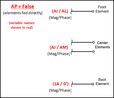
Each element is fed directly with an ideal current source. The back element is fixed at 1 amp magnitude at 0° phase. The center and front elements can be fed with any desired magnitude and phase. You may wish to use the optimizer to set variables AL and AM (phase for front and centers) and/or variables AI and AJ (magnitude for front and centers), experimenting with different optimizer targets and weights.
When "master switch" AP = True the feed system looks like this.
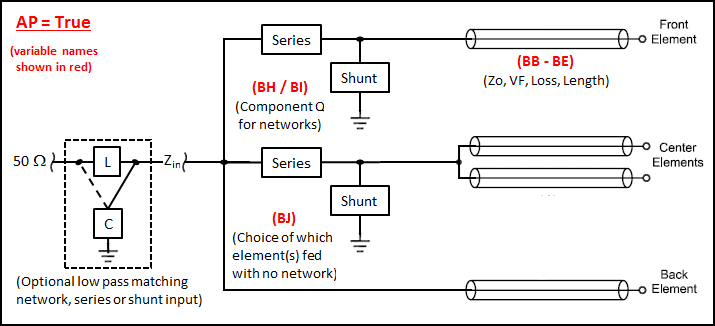
Using spare cells at the bottom of the Wires table, the model will transform the impedance (R/X) values at the element feedpoints (as calculated with AP = False) to corresponding impedance values at the network ends of the transmission lines. In addition, the magnitude and phase of the currents at the element feedpoints (per variables
AI-AM ) will be transformed to the magnitude and phase of the voltages at the network ends of the transmission lines. These transformed impedance and voltage values, which include the effects of line loss, are used to calculate the required component values for the phase shift networks. The results are shown on the Variables sheet merely for information.
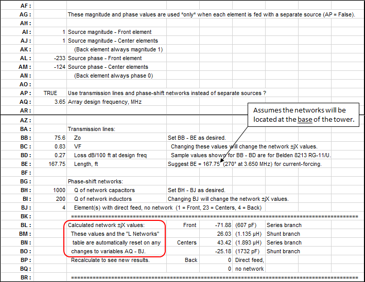
Note that the suggestion for transmission line length (BE) is not an absolute requirement. Although there are some advantages to using odd-λ/4 "current forcing" lengths, for this type of feed system the only absolute requirement is that the lines are long enough to reach from the element feedpoints to the central control box containing the phase shift networks.
Although line loss is included in the calculations, the network component loss due to finite Q for capacitors and inductors (variables BH and BI) is not included. That will result in an insignificant difference between the magnitude/phase ratios that you specified via
AI-AM and the calculated magnitude/phase ratios at the element feedpoints.

Even though the back element was fixed at 1 amp and 0° during the preliminary modeling (with AP = False) you are free to choose which elements are fed via phase shift networks and which element(s) are fed directly. That choice is made via variables BJ. All three choices will result in the correct magnitude/phase ratios to all elements but will yield different "Zin" R/X values and hence different SWR values. You can run a "variable sweep" on BJ to see the differences. Also, some choices may require unreasonable network component values.

Because you can choose any desired magnitude/phase ratios for the elements the resulting pattern can be tailored much more so than when using a hybrid coupler feed system. Here is a comparison between the "Lahlum/Lewallen" model with magnitude/phase ratios as shown above and the "Hybrid Coupler" model discussed earlier.
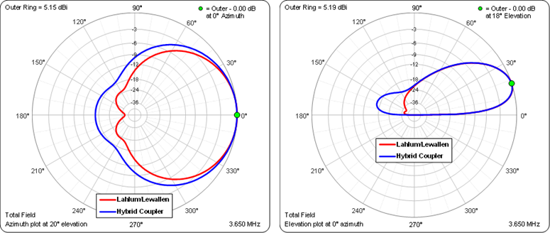
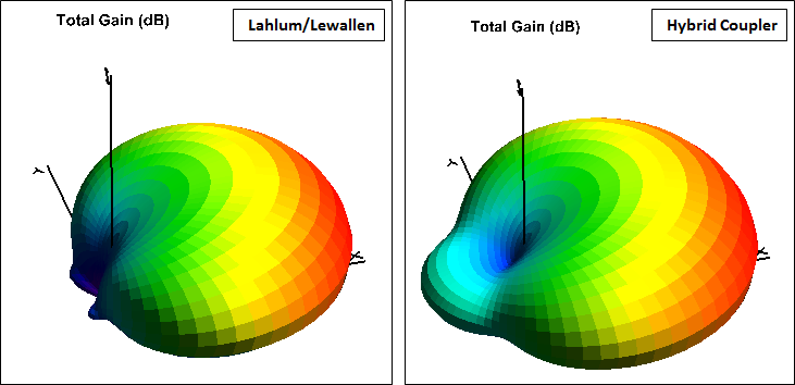
The trade-off is that the bandwidths are much narrower. Below, the vertical scale is the same as with the previous hybrid coupler feed system sweeps. The Lahlum/Lewallen model max Front/Back is ~40 dB, off-scale at top center.
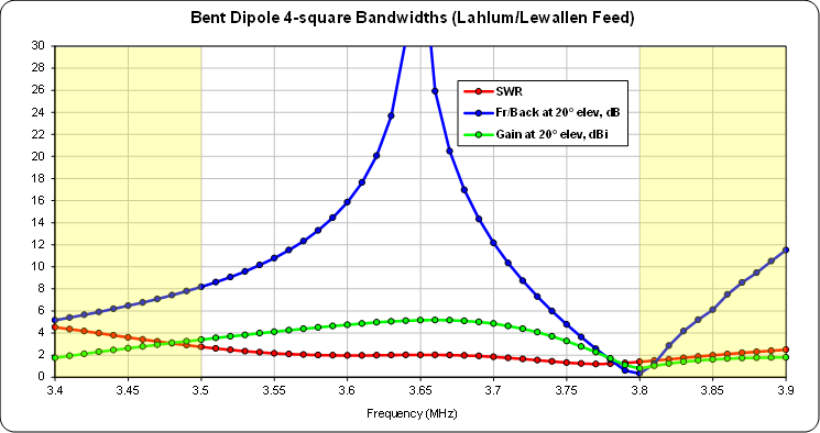
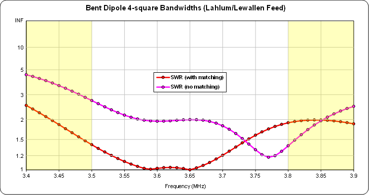
The problem is not really the slightly elevated SWR. That can be addressed by adding a simple matching network to the model using the Create Impedance Matching Network button.
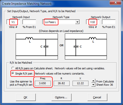
Below shows with and without the impedance matching network. Note the changed vertical scale.
The real issue is with the pattern bandwidth. Here is an animation showing the azimuth patterns from 3.5 to 3.8 MHz by steps of 25 kHz. The frequency for each frame is shown in the lower-right corner. For easy visual reference the blue trace shows the pattern at the array design frequency of 3.65 MHz. The annotation for the green dot marker (upper-right corner) shows how much the gain has decreased at each step. (For hints on how to stop the animation see here).
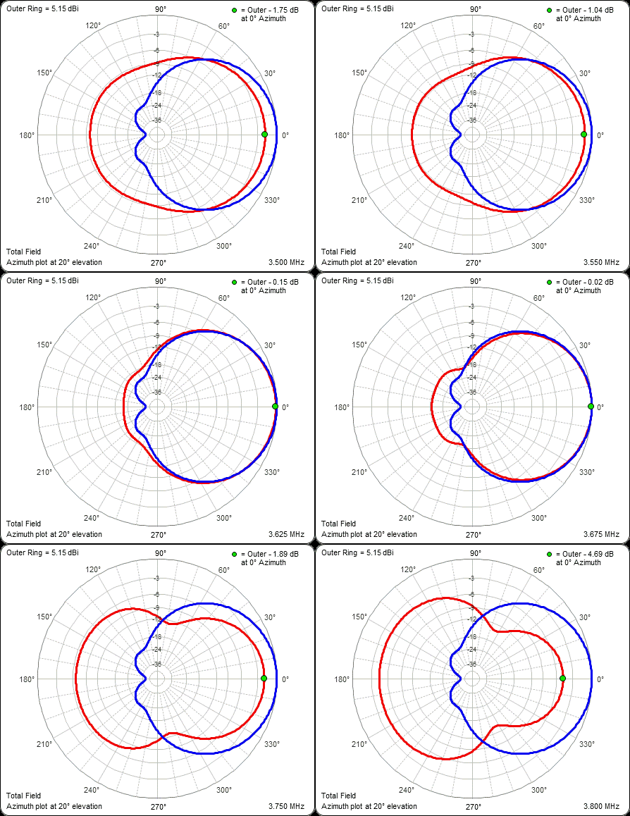
If you are interested in only a small segment of a given band you could tailor the pattern to meet your needs. If you want wide coverage on 80m the Lahlum/Lewallen feed system may not be the correct choice.
Parasitic Elements:
The final models to be discussed are not really 4-squares although the physical dimensions are similar.
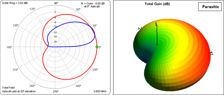
For the bent dipole parasitic example, only a single element is driven for a given direction and the other three elements are inductively loaded to act as reflectors. The loading is done by leaving one end of each parasitic element transmission line open as explained in the Christman et al. reference below.
The advantage of this feed system is much less complexity compared to an all-driven 4-square. The disadvantage is a reduction in forward gain of about 2 dBi and less rejection of high elevation angle signals. Here are the azimuth, elevation, and 3D patterns.
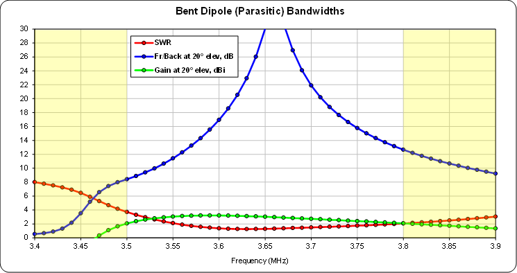
As with the Lahlum/Lewallen 4-square the bent dipole parasitic array has a relatively narrow Front/Back bandwidth.
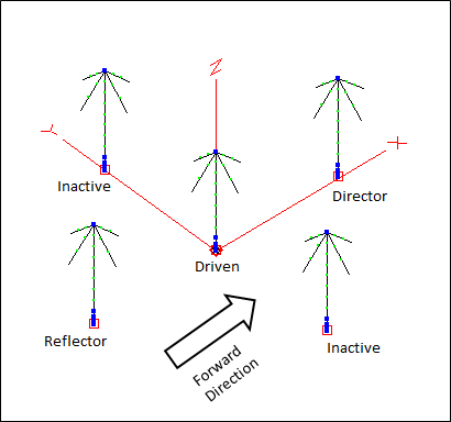
For a vertical parasitic example I chose a model described by N6LF in the article "A 3-Element 160 Meter Vertical Array". See the reference below. The antenna has the same physical footprint as a 4-square but has an additional element (and an additional radial field) in the exact center of the array. For radiation patterns aimed at any of the four quadrants, one element acts as a director, the opposite element acts as a reflector, the center element is driven, and the two "side" elements are made inactive by being open circuited at their feedpoints.
This antenna not only avoids the complexity of a 4-square feed system, it eliminates the need for all transmission lines except the main feedline to the center element. The front and back elements are switched between director and reflector mode by means of a simple relay which changes the amount of base-loading inductance.
Here is a view of the model including top-loading wires similar to what N6LF used.
And here are the azimuth, elevation, and 3D patterns.
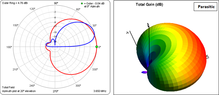
Although impressive looking, note that both the gain and pattern shape are very dependent on the ground loss in the radial system. In a private correspondence N6LF said that he is using 64 full-length (and overlapped) radials for each element. The modeled ground loss is set at 2 ohms. If you change that to 5 ohms you can see the degradation of the pattern.
Again, usable bandwidths are relatively narrow
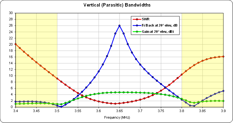
Bandwidths could be widened somewhat by using full-size rather than top-loaded elements.
Finally, for all of the models discussed above, no claim is made that they have been optimized for the "best" performance. That can only be done for each unique installation after considering site limitations and the necessary trade-offs between gain, pattern shape, unmatched SWR, and bandwidths.
Models:
The zip file below contains AutoEZ format (*.weq) models for both bent dipole and conventional vertical
4-square arrays. Detailed instructions can be found at the top of the Wires table for each model including a note concerning EZNEC segmentation check warnings that you may see with the hybrid coupler models and the steps needed to scale the model to a different band.Basic models:
With frequency sweeps including dumped power:
- Bent Dipole 4-sq Hybrid.weq
- Vertical 4-sq Hybrid.weq
- Bent Dipole 4-sq Lahlum.weq
- Vertical 4-sq Lahlum.weq
- Bent Dipole 4-el Parasitic.weq
- Vertical 3-el Parasitic.weq
- Bent Dipole 4-sq Hybrid sweep.weq
- Vertical 4-sq Hybrid sweep.weq
The "sweep" versions of the hybrid coupler models show the technique for including dumped power as a metric when running a frequency sweep from the Calculate tab. Those models also have modified coupler port shunts and modified element lengths in order to center the Front/Back and dumped power curves. Caution: In order to produce the correct results for dumped power make sure you have set EZNEC Options > Power Level as "Absolute V/I sources" and that you are using AutoEZ v2.0.13 or later.
Note that the "Bent Dipole" models do not include any wires to simulate the outside of the shield of the transmission lines. If desired you can add such wires at the end of the Wires table. For example, to include a wire running from the feedpoint of the front element to ground enter shortcut "w5e2" in any of the
End 1 X,Y,Z cells in an empty row at the bottom of the table. Then route that wire to match your proposed installation, eventually ending atX,Y,Z coordinates0,0,"=CE" which is the base of the tower, the "effective ground point" for the model. Change the wire diameter and number of segments as necessary. Repeat the steps for the remaining three elements using "w14e2", "w23e2", and "w32e2" as the start point and in all cases ending at0,0,"=CE" .If you intend to place common mode choke baluns on the transmission lines, add entries to the Loads table placing the loads at whatever position on the new wires that you intend to place the chokes and using your best estimate for the choking impedance, typically a few thousand ohms resistance and possibly some inductance.
For additional information on this subject see "Modeling Coaxial Cable" in the EZNEC Help.
The "Bent Dipole" models also do not include any wires to simulate Yagis or other antennas that might be attached to the tower, or to simulate other nearby antennas or conductive structures. Again, such wires can be added at the end of the Wires table.
References:
- Devoldere, ON4UN, Low-Band DXing, Chapter 11 - Phased Arrays (link)
- Devoldere, ON4UN, "Demystifying the Hybrid Coupler" (link)
- Gehrke, K2BT, "Vertical Phased Arrays", Ham Radio magazine, six part series, 1983-84 (link)
- Preedy, G3LNP, "Single Support Directional Wires" (link)
- Mitchell, K8UR, "The K8UR Low-Band Vertical Array" (link)
- Christman et al., K3LC (ex-KB8I), "The 160-Meter Sloper System at K3LR" (link)
An expanded version of this article appears in the ARRL Antenna Compendium Vol. 4.- Severns, N6LF, "Single Support Gain Antennas for 80 and 160 Meters" (link)
- Severns, N6LF, "Getting the Most from Half-Wave Sloper Arrays" (link)
- Severns, N6LF, "A 3-Element 160 Meter Vertical Array" (link)
- Ordy, W8WWV, "Using the Oscilloscope to Make Phased Array Measurements" (link)
- Ordy, W8WWV, "Measuring Complex Antenna Currents in a Vertical Array" (link)
- Maguire, AC6LA, "Phasing Lines for a 4 Square Array" (link)
Details for yet another feed method, the Christman/Lewallen "Simplest" all-transmission-line feed system.- Maguire, AC6LA, "Seeing the Effects of Phasing Lines" (link)
- Array Solutions Four Square Array Manual (link)
- DXE Transmit Four Square System Manual (link)
- Comtek ACB-4 Hybrid Four Square Array Manual (link)
- Wikipedia, Tower equivalent radius (link)
Line Lengths and Scope Traces for Lahlum/Lewallen Networks
Consider a vertical 4-square using magnitude and phase values as developed by Jim Breakall, WA3FET. The elements are fed as follows:
Front: 0.872 A / -218°The front and center elements are fed via phase shift networks, the back element is fed directly. For a model see the zip file at the end of this section.
Centers: 0.9 A / -111°
Back: 1 A / 0°As mentioned previously the model will use spare cells at the bottom of the Wires table (like an additional scratch pad area) to transform the element feedpoint impedances and currents to impedances and voltages at the input ends of the transmission lines. The transformed impedances and voltages are used to calculate the phase shift network reactance (±jX) values, which are then converted to inductance and capacitance values at the array design frequency.
If the transmission lines are precisely λ/4 long and have no loss the final steps of the calculations look like this.
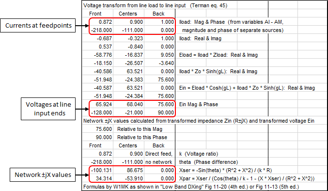
With no loss the transmission line characteristic impedance Zo is 75.6+j0. For all three lines:
Mag(Ein) = Mag(Iload) * ZoYou can verify that by looking at the back element transmission line values above.
and
Phase(Ein) = Phase(Iload) + 90Mag(Ein) = 1.0 * 75.6 = 75.6The same relationship is true for the other transmission lines.
Phase(Ein) = 0.0 + 90 = 90The network component values are summarized in the scratch pad area of the Variables tab.

After sending the model to EZNEC these are the results.

Recall that network component loss is not included in the formulas for component reactance which is why the feedpoint current magnitudes of 0.869 and 0.895 are just slightly less than the expected 0.872 and 0.9 relative to the back element.
If the transmission lines have realistic loss of 0.27 dB/100ft at 3.65 MHz the EZNEC results look like this.

Using the revised voltages at the input ends of the lines, the network component values have been automatically recalculated to produce exactly the same element feedpoint currents, front
0.869 A / -218° and centers0.895 A / -111° . You could measure the feedpoint currents using current probes or you could simply measure the voltages at the input ends of the lines. In the latter case the traces on an oscilloscope would look like this.
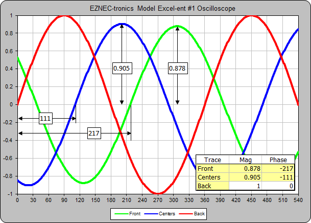
Note that it's the ratios of the magnitudes and the differences of the phases that matter, not the absolute values. Also, even though you are measuring relative voltages of
0.878 / -217° and0.905 / -111° , which are not the relative currents of0.872 / -218° and0.9 / -111° that you want, the feedpoint currents will indeed be correct (less the minor difference due to network component loss).Now, suppose that the lines are not λ/4 long but instead are an arbitrary 100 ft which is about 161° electrical length at 3.65 MHz. In that case the EZNEC results look like this.

The feedpoint currents are the same (except for a very minor difference due to network component value rounding to the closest picofarad and nanohenry) but the voltages at the input ends of the lines are completely different. However, you could still measure the voltages with an oscilloscope and be assured that if the voltages matched the calculated relative magnitude ratios and phase differences, the element feedpoint currents would be correct. (Below, note the revised vertical scale.)
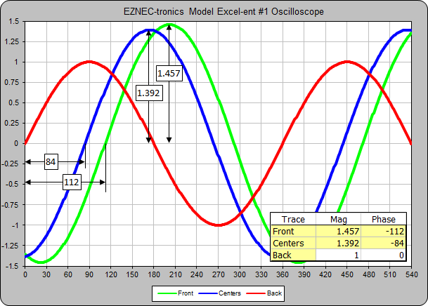
Of course you must know the characteristics of the transmission lines in order to do the calculations. (Actually, in order for the model to do the calculations.) But the characteristics are easily measured and that is probably no more prone to error than a) any perturbations that the insertion of current probes might cause and b) any current probe measurement errors due to the probe lines introducing changes in magnitude or phase because the probe line load is not exactly equal to the probe line Zo (that is, the probe line is not completely "flat").
One of many different ways to measure the characteristics of a transmission line is to use the "T-Line Measure.xls" workbook available here.
The zip file below contains an Excel workbook named "ScopeTraces.xls" which was used to produce the above graphics, as well as model file "Vertical 4-sq WA3FET.weq" which was used for the examples in this section.
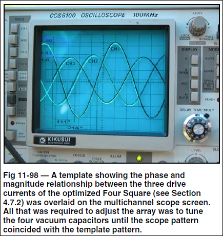
And here's a tip from ON4UN: Resize the Excel chart such that the plot area is the same size as your scope screen. Print the chart on a transparency and trim away the excess outside the plot area. Overlay the transparency on your scope screen. Adjust the scope controls so that the reference traces match. Then all you have to do is adjust the phase shift network component values until the scope traces for the elements fed via networks match (underlay) the calculated traces. When that is the case the element feedpoint currents will be correct. This color version of Fig 11-98 from the 5th edition of Low-Band DXing shows ON4UN using the transparency overlay trick.
Be sure to read the W8WWV "Using the Oscilloscope to Make Phased Array Measurements" page (link).
Modeling Intersecting and Bus-Wired Radial Fields
As stated in a previous section, the radials for conventional vertical elements are normally simulated by connecting the elements directly to MiniNEC-type ground and then adding a resistance at the base of each element to account for ground loss. I've always been curious as to how that technique might compare to modeling the actual radials, either slightly above ground (essentially "almost on ground") or buried.
Models have been created (see zip file at the end of this section) in which the number of radials can be set as 4, 8, 16, 32, 64, or 128 just by changing a single variable. Below is an animation of the top-down view of a
4-square array as the number of radials is changed. The small red circles indicate the positions of the four vertical elements.
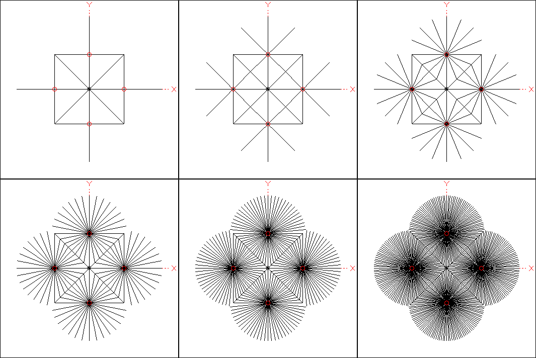
Other variables allow you to change the spacing of the vertical elements (and hence the hubs of the radial fields), the maximum length of each radial (if not truncated where it joins the radial from an adjacent field), whether or not to include bus wires (where the radials interconnect) in the model, and whether or not to bury the radials slightly below ground (if using a NEC-4 engine).
Each radial is actually multiple collinear wires with tapered segment lengths, very short segments near the hub and longer segments at the periphery. That yields more accurate results with a smaller total number of segments. Even so, setting the number of radials to 64 requires ~3000 segments (depending on the length of the shortest segments) and 128 radials requires ~6000 segments. Hence those two choices are available only if you are using EZNEC Pro/2 or Pro/4.
Determining the length of any truncated radials takes a bit of trigonometry as explained on this page and in the diagram below. The truncated radial being studied in this example is indicated by the heavy red line, shown in relation to the complete radial system on the left and isolated on the right.
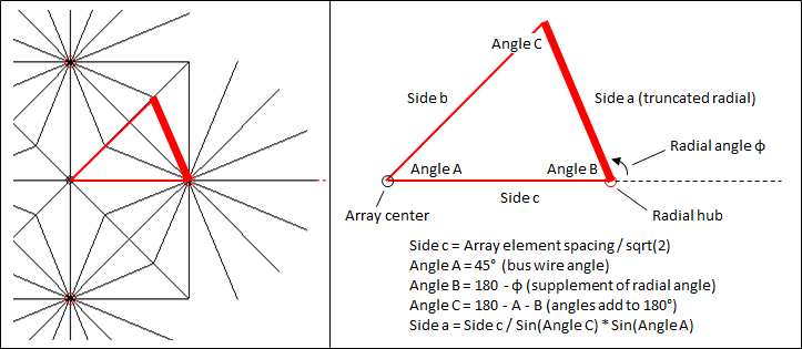
To calculate the length of side a (the truncated radial) requires knowing the length of side c along with angles A and C. Side c is known since the spacing between adjacent elements in the array is known (set via a variable). Angle A is fixed at 45 degrees and angle B is the supplement of radial azimuth angle φ. The step size of radial azimuth angle φ depends on the number of radials specified. For example, with 16 radials the radial angles are 0, 22.5, 45, 67.5, 90, 112.5 (example above), 135, and so on. With angles A and B known angle C can be determined since the three angles of a triangle always add to 180 degrees. Now the length of the truncated radial (side a) can be calculated. With the length of the radial determined and knowing the azimuth angle for this particular radial, the XYZ coordinates for the outer end of the radial can be calculated for use in the Wires table.
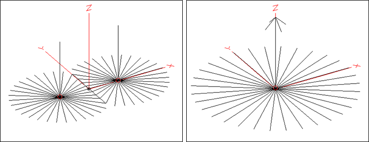
Additional radial study models have been developed for a 2-element array (below left) and for a single vertical element (below right). The view of the single element model below also illustrates an additional feature available with all models, the ability to add top-loading capacity hat wires.
Now to the question of how the "with radials" configuration compares to the "MiniNEC ground with added loss" configuration. First let's look at a single ~λ/4 vertical, no top-loading, with the radials buried 1 inch below the surface. The number of radials (variable AC) is varied from 4 to 64. All radials are 65 ft long; none are truncated. As the number of radials is changed the length of the vertical element (variable D) is adjusted for resonance. All calculations for this and the following tests were done using the EZNEC Pro/4 v6 NEC-4D engine with "Real/Extended Accuracy" (GN3) ground and "Average" (0.005, 13) characteristics. At 3.65 MHz, λ/4 in free space is 67.37 feet.

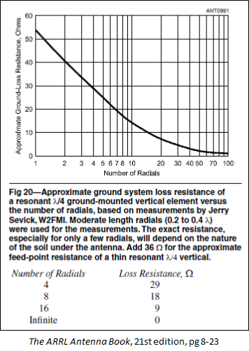
No surprises here. As the number of radials is increased the feedpoint resistance approaches the theoretical ~36 ohms and the gain in dBi improves. To simulate the radials with MiniNEC ground you can just add a resistive load with a value of what is shown above as ground loss. This approximately matches the chart which is in Chapter 8, section "Phased Array Design Examples" of recent editions of The ARRL Antenna Book, reproduced below.
Now suppose instead of burying the radials you just lay them down on grass that has been cut very short. Assume that the thickness of the grass and thatch is 1 inch. When dry this is mostly air so the modeled radials will be 1 inch above the actual ground surface. All radials are still 65 ft long.
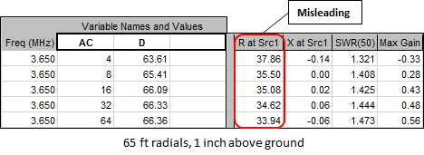
What's going on? Although the gain improves as the number of radials is increased, as expected, it seems that with 4 radials the ground loss is only a few ohms and with 64 radials there is negative ground loss. That can't be.
It isn't, and this is not an error in the NEC modeling. Although the length of the vertical element has been adjusted for overall antenna resonance, the maximum current does not occur at the feedpoint. Instead, the maximum current is found on the radials some distance away from the feedpoint. And because of that the feedpoint impedance will not be the same as when the radials are buried.
Below is a comparison of the current distribution on one (of four) radials when the radials are elevated 1 inch above ground (red trace) or are buried 1 inch below ground (blue trace). The current at the feedpoint (base of vertical) is 1 amp and since there are 4 radials the total radial current is 4 times what is shown on the chart. Segment lengths of the radial have been modified to be all the same (all 0.1 ft, not tapered length segments), hence the distance along the horizontal axis corresponds to the distance away from the radial hub.
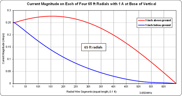
When the radials are buried the radial current peaks at the hub and decays exponentially. When the radials are above ground (and are 65 ft long) the radial current peaks about 15 feet out from the hub and has a sinusoidal shape.
Suppose the radials are "tuned". That is, the length of each radial is half the length of a resonant dipole at the same height and with the same ground characteristics. Here is a similar comparison of current distribution when all radials are 48.1 ft long. That's about 0.18 free space wavelengths at 3.65 MHz.
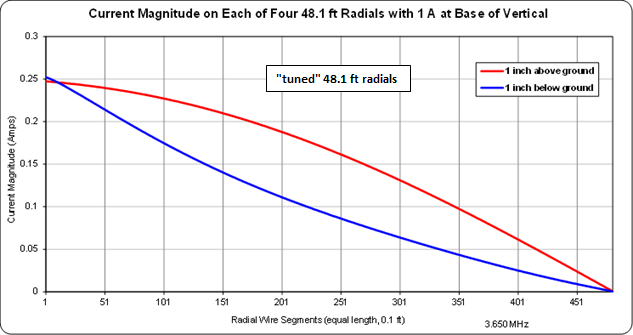
The buried radials have a similar current pattern as before although the decay is not as rapid. The above ground radials now have the current maximum at the hub, or nearly so.
The "exponential for buried versus sinusoidal for above ground" current distribution has been measured by W7EL, N6LF, and probably others. Unless your radials are in direct contact with dirt they will exhibit the sinusoidal current distribution. Whether or not this makes a difference depends on the length and number of radials,
Below are the feedpoint impedance and pattern gain calculated values with the radials at 48.1 ft instead of 65 ft, again with the length of the vertical element adjusted for resonance as the number of radials is changed. For comparison, the same test cases were also calculated using the NEC-2D engine with "Real/High Accuracy" (GN2) ground. (With the NEC-2D engine the vertical element lengths for resonance are slightly different, not shown.)

This seems more reasonable. Subtracting 36 ohms it now appears that 4 "tuned" radials 1 inch above ground equates to about 11 ohms of ground loss, 16 radials equates to about 6 ohms, and 64 radials equates to about 4 ohms. Those values are what you would add as a resistive load if using MiniNEC ground.
With the NEC-2D engine you will see segmentation check warnings since the smallest segment length (and radial height) of 0.083 ft (1 inch) is
~0.0003 λ, less than the recommended minimum for NEC-2 of0.001 λ. However, the calculated results are very similar to the NEC-4 results so it appears that the warnings can be ignored, at least for this radial height.So should you really go to the trouble of "tuning" the radial lengths if you intend to place the radials on top of low-cut grass? Probably only if you plan to use a small number of radials.
Now on the scenario of a 4-square radial field with intersecting and bus-wired radials. With the 4-square radial study model you can include just a single vertical element while keeping all four radial fields. (That is, all four "quadrants" of the complete radial system.) This is analogous to what you might do when adjusting each individual element of the physical array, with the other elements either removed or open circuited.
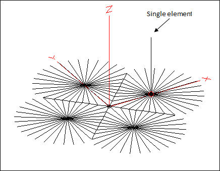
With the model configured as above here are the calculated results using a varying number of radials in each field, for both below ground and above ground fields. Radials that are not otherwise truncated at a junction are 65 ft long. (Note that half of the radials that are attached to the single vertical element are in turn attached to other radials and to the bus wires, hence there really is no point in trying to "tune" the lengths.) Calculations were done using the NEC-4D engine with "Real/Extended Accuracy" (GN3) ground.
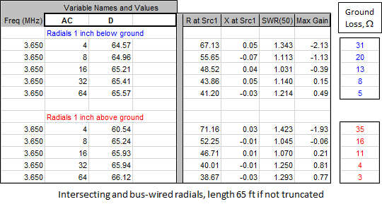
Approximate ground loss was again determined by subtracting 36 ohms from the feedpoint resistance values. However, that's for a single vertical element. When all four elements are included in the model, and when those elements are fed with the desired current magnitude and phase, the mutual coupling between the elements makes things more complicated.
Here is a comparison of the element feedpoint impedance values when the radial fields are included in the model versus when MiniNEC ground is used with added ground loss (variable BA, with values per the tables above) to simulate the radials. The front element is fed with
0.872 A / -218° , the center elements are fed with0.9 A / -111° , and the rear element is fed with1.0 A / 0° . The feedpoint R/X values would be different with other magnitudes and phases at each source.For below ground radials:
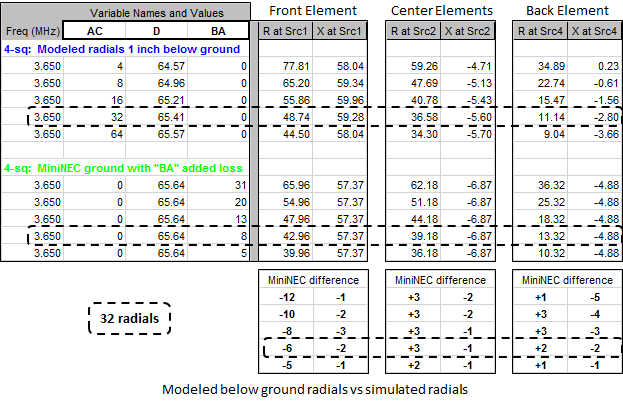
The results for 32 radials, either included in the model or simulated via added ground loss, are outlined merely to make visual comparison easier for a typical situation.
For above ground radials:
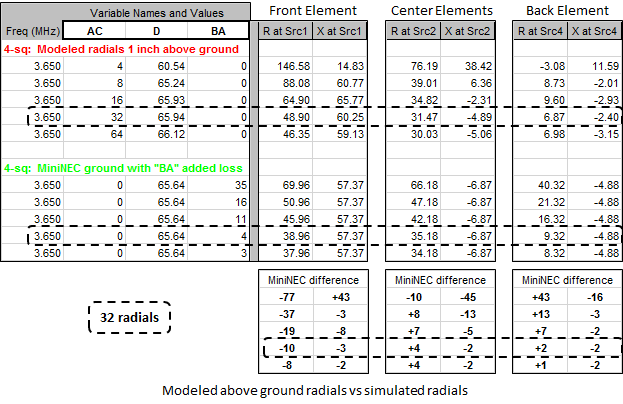
For 32 and 64 radials the impedance values are reasonably close but by no means equal. And if you intend to model the 4-square feed system you'll want the element impedances to be as exact as possible.
To make the model using MiniNEC ground more realistic, instead of adding the same fixed resistance to each element you could add whatever complex R±jX it takes to make each source impedance equal to its counterpart in the "with radials" model. That is, run the "with radials" model with just a single element but with all four radial fields and adjust the element length for resonance. Be sure to use the ground characteristics for your location which may not be "Average". Then run the model with all four elements and with your desired current magnitude and phase ratios to determine the feedpoint impedance values. Finally, use those impedance values to modify the MiniNEC model, again after adjusting a single element for resonance.
For example, in the case of 32 below ground radials, rather than adding a fixed resistance of 8 ohms to each element you could add 13.78+j1.92 ohms to the front element, 5.40+j1.26 ohms to the two center elements, and 5.82+j2.08 ohms to the back element. Here's a comparison at three different frequencies.
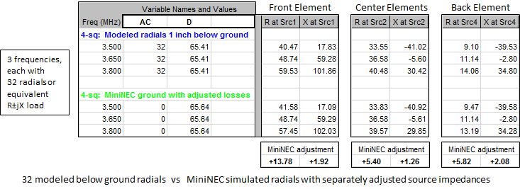
The MiniNEC results will match the "with radials" model almost exactly at the design frequency (there will be very minor differences in the radiation patterns) and will be very close at other frequencies. Then when you add a feed system to the MiniNEC ground model you won't have to deal with hundreds or thousands of segments as you experiment with the feed system parameters or run frequency sweeps.
Models:
The zip file below contains these AutoEZ format (*.weq) models:
RadialStudyModels.zip
- Vertical 4-sq Intersecting Radials.weq
- Vertical 2-el Intersecting Radials.weq
- Vertical with Tapered Seg Radials.weq
It is strongly suggested that you use AutoEZ v2.0.24 or later with these models. That maintenance update has several enhancements to improve performance when dealing with models that have thousands of wires. (Recall that each radial "wire" is actually multiple collinear model wires with tapered segment lengths.) See AutoEZ Change History and Update Instructions for more information about maintenance updates.
Hint: The 4-sq model, when set to have 32 radials 1 inch above ground, normally requires 1572 segments. If you are using EZNEC+ v5 with a 1500 segment limit you can change variable AK (min segment length) from 0.083 to 0.110 ft. The number of segments will be reduced to 1492. Changing AK will raise the height of the radials from 1 inch to ~1.3 inches. If you then want to set the radial height back to 1 inch, override the formula for AQ (element base height, also radial height for above ground radials) by typing in 0.083. That will violate NEC guidelines just slightly but the calculated results will be essentially the same.
The same advice about setting AK=0.110 applies to all of the above models when configured for 128 radials. In that case the angle between adjacent radials is a very acute 2.8 degrees. If AK is left at the default of 0.083 you will see EZNEC Geometry Check errors of the form "Center of wire x end segment within wire y". The errors can be avoided by increasing the value for AK (min segment length). For more information about this error see "Geometry Check" in the EZNEC Help.
For additional information about simulating "almost on ground" radials see EZNEC Help section "Elevated Radial Systems". Don't be misled by the wording, the topic is about radials placed near the surface of the ground. And to add to the confusion, the three models above can be configured to place the radials at typical "elevated" heights of perhaps 8 or 10 feet above ground if desired.
References:
- Severns, N6LF, "A Closer Look at Vertical Antennas With Elevated Ground Systems" (Part 1, Part 2)
- Maguire, AC6LA, "Modeling for the N6LF 'Elevated Radials' QEX article" (link)
- Severns, N6LF, "An Experimental Look at Ground Systems for HF Verticals" (link)
The above is a QST article summary of a seven-part QEX series "Experimental Determination of Ground System Performance for HF Verticals".
- Part 1 - Test Setup and Instrumentation (link)
- Part 2 - Excessive Loss in Sparse Radial Screens (link)
- Part 3 - Comparisons Between Ground Surface and Elevated Radials (link)
- Part 4 - How Many Radials Does My Vertical Really Need? (link)
- Part 5 - 160 Meter Vertical Ground System (link)
- Part 6 - Ground Systems for Multiband Verticals (link)
- Part 7 - Ground Systems With Missing Sectors (link)
- Severns, N6LF, "The Case of Declining Beverage-on-Ground Performance" (link)
- Maguire, AC6LA, "Feed Systems for Two Element Arrays" (link)
Alternative 3D Plots for EZNEC Pro/4 Users
If you are a user of EZNEC Pro/4 then you have a NEC-4 license. On the NEC-4.2 CD that you received from Lawrence Livermore National Laboratory (LLNL), in the .\NEC42\Windows_Exe\NECPLOT\NECPlotG folder, there's a program named NECPlotG along with its documentation. That program was used to produce the 3D radiation plots shown in the first section of this page. (If you have the earlier NEC-4.1 CD you can get a replacement by sending an email to LLNL with the details of your NEC-4 license.)
In order to simplify the use of NECPlotG with AutoEZ I have created a small helper Excel workbook named "PF3_to_OUT.xls" (link). Unzip and place that workbook in the AutoEZ home folder, typically C:\AutoEZ. Also place a copy of the NECPlotG.exe program in that same folder. Then to produce a 3D plot follow these steps.
1) On the Calculate tab enable (check) the Include 3D Data in Calculations option and calculate one or more test cases.
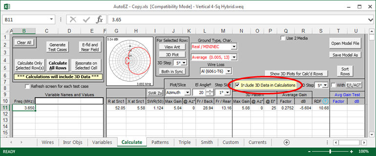
For each test case an OpenPF 3D format (*.pf3) file named $AutoEZ$n.PF3, where "n" is the test case number, will be written to the AutoEZ home folder.
2) With Excel, open the PF3_to_OUT.xls workbook and enable macros, ignoring the dire warning from Microsoft that your wife will leave you, your dog will bite you, and your house will burn down if you do so.
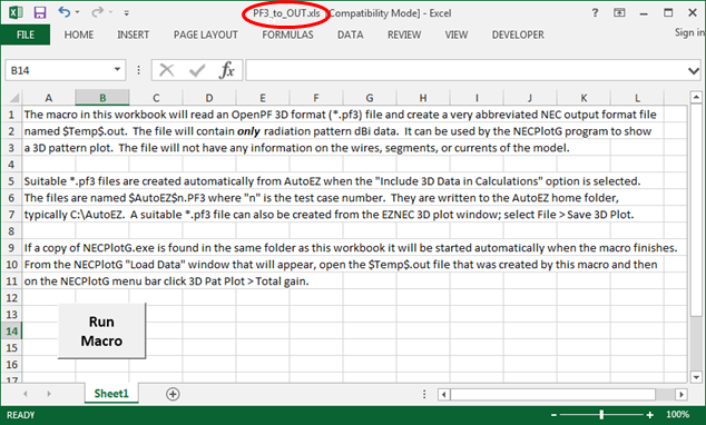
Click the Run Macro button and open a *.pf3 file such as $AutoEZ$1.PF3 for the first test case. A file named $Temp$.out will be created and (if present) the NECPlotG program will be started. The first step of that program is to show its "Load Data" dialog window. Load (that is, open) the $Temp$.out file just created.
After loading the $Temp$.out file the NECPlotG window will look like this.
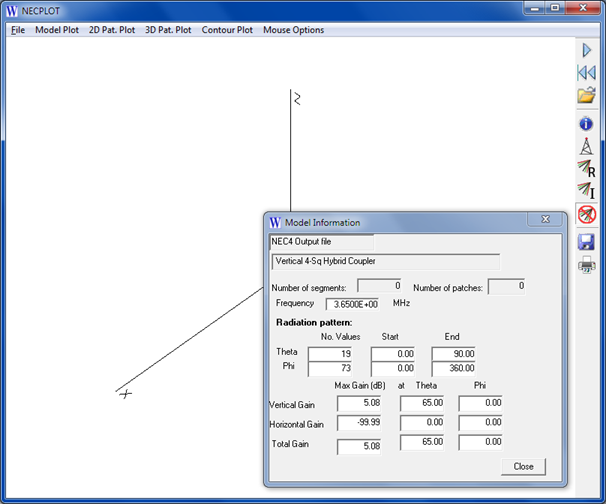
3) On the NECPlotG menu bar click 3D Pat. Plot > Total gain.
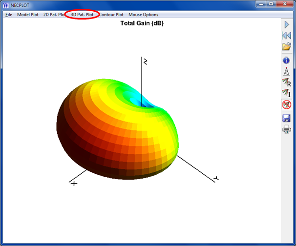
You can manipulate the plot using the mouse buttons, mouse wheel, and keyboard arrow keys. The default actions are:
To change the default actions use the Mouse Options menu choice. Note that "Mouse Options > Cursor" really means "Keyboard Arrows". There is no choice for the mouse wheel, which always zooms.
- Drag with left mouse button held down — Rotate
- Drag with right mouse button held down — Pan
- Keyboard up/down keys — Zoom
- Mouse wheel — Zoom
4) Optional, to show the gain at any point on the surface of the pattern click 3D Pat. Plot > Gain Probe.
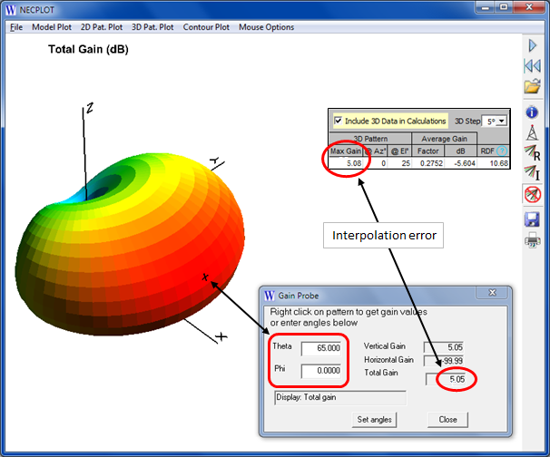
You can then either right-click anywhere on the pattern or set explicit Theta/Phi angles. The gain shown in the dialog window is interpolated from the surrounding four points so the displayed value will not exactly match the actual 3D pattern gain (5.05 dBi vs 5.08 dBi in this example). Using a smaller 3D step size will reduce the discrepancy.
Finally, note that the Model Plot > Plot and 3D Pat. Plot > Model plot inset choices are not available in this scenario. Those choices are similar to the EZNEC "View Antenna" window and the $Temp$.out file does not contain any information on the wires of the model.