Top hat vertical, 16 spokes
Before reading this section you may wish to review the description of the AutoEZ Replace XYZ Numbers with Formulas feature.
EZNEC has many different ways to create models with straight numeric coordinate values. In the "Replace XYZ Numbers with Formulas" section you saw how to convert those numeric values to Excel formulas which can be controlled via test case rows on the Calculate sheet. This section will show how to combine some of the EZNEC model-building functions with the AutoEZ "Replace XYZ Numbers with Formulas" feature to create a
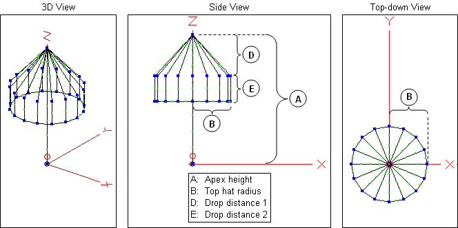
"variable-ized" version of a somewhat arbitrary model. You may or may not have an interest in this particular type of antenna, but you might be able to apply some of the EZNEC model-building techniques to your own models.The model to be built in this example is a "Top Hat" vertical for 40 meters. The top hat consists of 16 sloping wires, perhaps guy wires leading from the apex, connected to 16 vertical wires. The lower ends of the vertical wires are connected with a perimeter wire. Believe it or not, all dimensions of this antenna will be controlled with just a few variables.
Using EZNEC, not AutoEZ, open EZNEC sample model VERT1.EZ. The EZNEC samples are typically found in "C:\Program Files [(x86)]\EZW\Ant". (The "(x86)" part will be present on
64-bit machines.) Bring up both the View Ant window and the Wires window. If necessary,re-size andre-position the windows so you can see both. That way as you make changes on the Wires window the results will be immediately visible on the View Ant window.In the Wires window, click on any of the
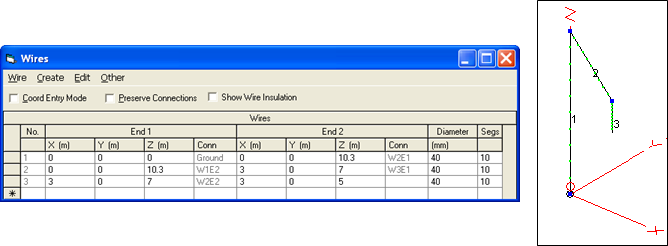
End 1 X,Y,Z cells in the "add row", the empty bottom row of the input grid. Type "w1e2" (without quotes) and press Enter to setEnd 1 of the new wire equal toEnd 2 of wire 1. The "w1e2" notation is the very useful "Connect End To" shortcut for quickly defining all 3 X,Y,Z coordinate values for one end of a wire. Tab right or use the right arrow key to move to theEnd 2 X coordinate cell for new wire 2. Change theEnd 2 X,Y,Z values from the default (0,0,0) to (3,0,7).Create another new wire with
End 1 values of "w2e2" andEnd 2 values of (3,0,5). You've now created a sloping wire (wire 2) with a drop of 3.3 meters (10.3 minus 7) and a vertical wire (wire 3) with a further drop of 2 meters (7 minus 5).End 1 of wire 2 is connected toEnd 2 of wire 1 andEnd 1 of wire 3 is connected toEnd 2 of wire 2.
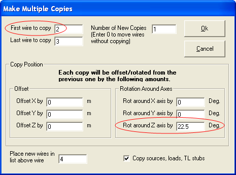
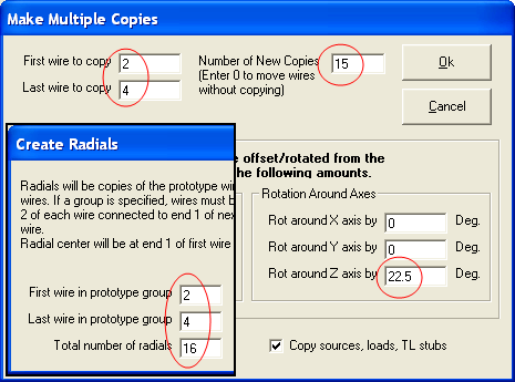
If using EZNEC+ or EZNEC Pro: In the Wires window, click on the menu item 'Wire' and then select Make Multiple Copies. In the dialog window that appears change the "First wire to copy" from 1 to 2. Change the "Rot around Z axis by" from 0 to 22.5. Click OK. Back in the wires window, add another new wire (6) going from w3e2 to w5e2. Then click the button on the left side of the wire 4 row to select the entire row. Hold down the Shift key and click the button to the left of the wire 5 row. With both wires 4 and 5 selected press the Delete key to remove those wires. What was wire 6 will become wire 4.
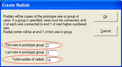
If using EZNEC Std or EZNEC Demo: These EZNEC program types do not have the Make Multiple Copies function but you can accomplish the same thing using Create > Radials. Change the "First wire in prototype group" from 3 to 2 and change "Total number of radials" from 4 to 16. Click OK. As above, add another new wire (34) going from w3e2 to w5e2. Now delete wires 4 through 33. What was wire 34 will become wire 4.
No matter which EZNEC program type you are using you have just created a new wire 4 which has a particular length and a particular angle needed for the final step. Now you can use either Wire > Make Multiple Copies or Create > Radials to finish the model as shown below.
Back on the Wires window, notice all the unique
End 1 andEnd 2 X/Y values. Unless your trigonometry skills are a whole lot better than mine it would have been difficult to come up with those values directly. Also note in the "Conn" (Connection) columns that with the exception ofEnd 1 of wire 1, all wires have both ends connected to other wires in the model.On the EZNEC main window click on the Description Title just below the menu bar. Change the description to "Top Hat Vertical". Then save the model with filename TopHatVertNumeric.EZ, clicking No when asked if you want to also save the current Antenna Notes.
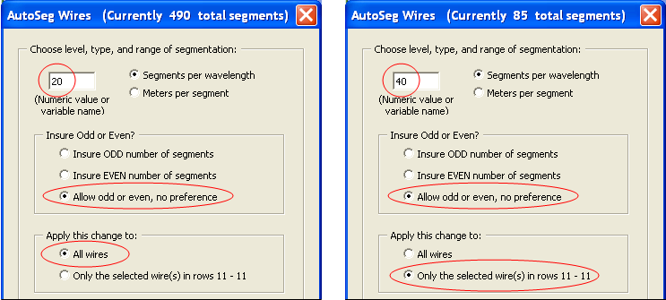
Start AutoEZ if necessary and open this new model file. On the AutoEZ Wires sheet note that the number of segments is 490. That's because each of the 48 new wires that were created had, by default, the same number of segments (10) as wire 1 of the original VERT1.EZ model and wire 1 is more than twice as long as any of the other wires. So the first thing to do is click the AutoSeg button and change the segmentation density for all the wires to a more reasonable value like 20 segments per wavelength. After that you can then select any cell in row 11, the row for wire 1, click the AutoSeg button again and enter twice the segmentation density for that single wire.
It is not necessary to use the same segmentation for all wires of a model. In this case the top hat wires will each carry much less current than the main vertical wire and wires with less current can have lower segmentation density. Now the model has a more reasonable 90 number of segments.
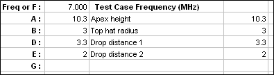
Tab to the Variables sheet and make the following entries.
Back on the Wires sheet click the Formulas button then on the TempEdit sheet click the Replace Numbers with Formulas button. Start the replacements with the Z coordinates since those are the easiest. Click on one of the "10.3" values for Z coordinates, enter the formula "=A", and just to be safe
un-check the "X coords" and "Y coords" boxes knowing that the next few replacements should apply only to Z coordinates. Apply and note that the number of replacements is 17, consisting ofEnd 2 of the main vertical wire andEnd 1 of 16 sloping top hat wires.Select one of the "7" Z coordinate values and apply
"=A-D" as the replacement formula. Number of replacements 32,End 2 of 16 sloping top hat wires andEnd 1 of 16 vertical wires. Repeat for one of the "5" Z coordinate values but this time use the formula"=A-D-E". Number of replacements 48,End 2 of 16 vertical top hat wires and both ends of 16 perimeter wires.Now it's time to do the X/Y coordinates.
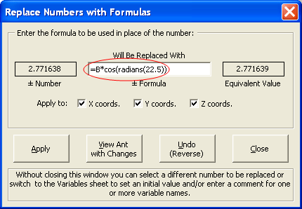
Re-check the "X coords" and "Y coords" boxes. Select one of the "3" values and enter the formula "=B". Apply the change. Without closing the dialog window, select one of the "2.771638" values. Expand the formula by typing"*cos(radians(22.5))". Variable B is the radius of the top hat, "cos" is the Excel cosine function which expects its argument to be in radians, "radians" is the Excel function which converts degrees to radians, and "22.5" is the angle in degrees of this spoke in the XY plane. Remember you can type the formula in upper, lower, or mixed case. Also remember that as you type the formula is re-evaluated for each new character entered. If what you have typed so far is not a valid Excel formula you will see "???" in the "Equivalent Value" field.
Apply the change. Again without closing the dialog window, select one of the "2.12132" values. Then, rather than re-typing the whole formula, just change the "22.5" portion to "45".
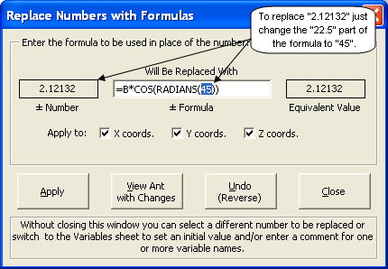
Recall the "matching tolerance" concept discussed in an earlier description of the Replace Numbers with Formulas button. For instance, when you replace "2.12132" AutoEZ will find and replace "2.12132", "2.121321",
"-2.121319", "-2.121321", and"-2.12132" with the formula you typed or its negative equivalent.Apply the change and repeat for "1.148051" using angle "67.5". After that there is no need to replace X/Y values of "0" with a formula using an angle of "90". No matter how variable B might be changed in a test case row, "=B*COS(RADIANS(90))" will always be "0".
One final change. Note that the diameter for all the wires is 40 mm, roughly 1.5 inches. As was the case with the initial segment counts, the diameters are all the same because when you created the new wires in EZNEC they were all given the same diameter as the first wire. To change the diameter for the top hat wires to something like #12 you could use the Edit: Find / Replace button to replace "40" with "#12".
However, "40" is not a very unique string. If you were working with a model that had several dozen wires still with straight numeric values for the XYZ coordinates along with straight numeric values for the segment counts, Excel may find and replace "40" with "#12" in cells other than where you intended even if you are careful to check the "Match entire cell contents" box. To prevent this, first click on the "H" column header to select the entire H column. Then when you use Excel's Find/Replace the search will be limited to just that column.
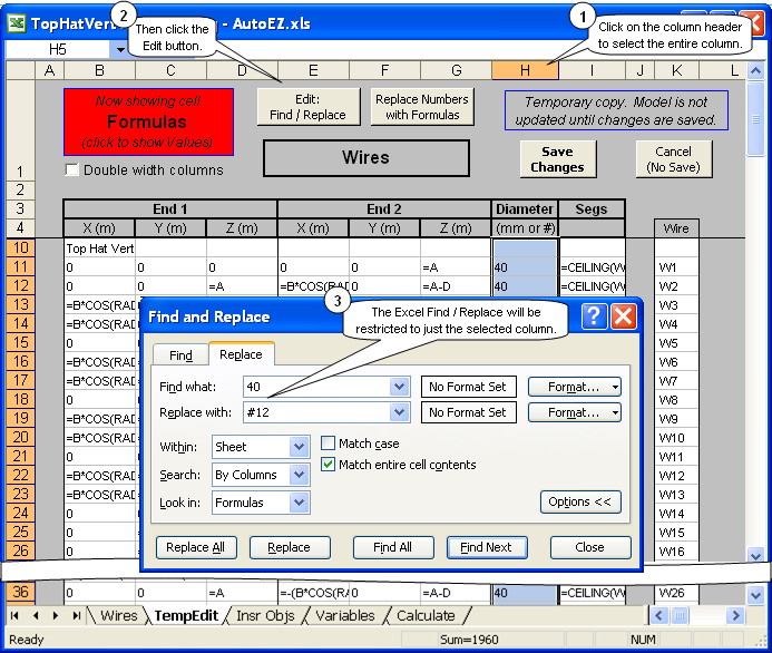
Caution: If you click Find All prior to Replace All, Excel will
un-select the column and change the selection to just a single cell. If you fail to notice that and then click Replace All the replace operation will include the entire sheet, not just the particular column you intended.After you have made the replacements go back and reset the diameter for just wire 1 by manually entering "40" into cell H11.
Save the changes you have made. Except for the "0" values, all of the XYZ coordinates for this model are now controlled by formulas using one or more of the variables A, B, D, and E. You can create test case rows on the Calculate sheet changing these variables as desired. You can also manually change the variable values on the Variables sheet and then view the model to see the new configuration.
"Mark out" wires using a formula
Now suppose you want to create a model such that the top hat has sloping wires and horizontal perimeter wires but without vertical wires.
If you set E (the drop distance for the vertical wires of the top hat) to 0 then the horizontal perimeter wires will "move higher" and connect to the sloping wires, but you'll get an error message for the vertical wires (now length 0) concerning either segments or wire length. So do you have to construct a completely new model without the vertical top hat wires? Not at all. You can "mark out" the vertical wires. When you "mark out" one or more wires (similar to "commenting out" a line of code if you have a programming background), the "marked" wires are not included in the temporary model file that is sent to EZNEC.
The vertical wires of the top hat are wires 3, 6, 9, ... 48. On the Wires sheet you could enter an "x" in column A for each of these wires whenever you want to exclude them. But there's an easier way. "Mark" the wires using a formula.
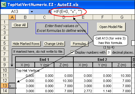
Select cell A13 (13 is the row for wire 3). In the formula bar, near the top of the Excel window, enter the formula shown above. The Excel "IF" built-in function has the syntax "IF(logical_test, [value_if_true], [value_if_false])". That is, Excel checks whether a condition is met and returns one value if true or another value if false. In this case if the value for E is 0 the wire will be "marked" with an "x" character. But if the value for E is not 0, a null string ("") is used. Entering a null string is the same as entering nothing at all so the wire is not marked.
After you have entered that formula in cell A13 press Ctrl-C to copy. Now press the keyboard down arrow 3 times to move to cell A16 (the row for wire 6). Press Ctrl-V to paste. Down arrow 3 times again, Ctrl-V. Down arrow 3 times again, Ctrl-V. (Hint: Right hand one finger for the down arrow, left hand two fingers for Ctrl-V.) Repeat until you have done cell A58 (the row for wire 48). When you finish press Esc to clear the moving border around cell A13, the original cell that was copied.
Caution: If you have already set E to 0, every time you "mark" a wire using this formula the wire numbers in the "For Information Only" column K will change. This might be confusing so you should make sure E is non-zero before marking the wires. Also note that here you do not want to use the "copy - paste special - values" technique discussed in earlier examples. In this case you really do want to copy and paste the formula for a cell.
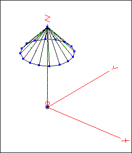
Tab to the Variables sheet, manually set E to 0, and press the View Ant button on that sheet. Presto. You can also tab back to the Wires sheet and note that what were wires 3, 6, 9, ... have been "marked out". Set E to some non-zero value and all these same wires will be "unmarked".
Don't confuse "marking" one or more wires with use of the Hide Marked Rows button. When you "mark" a wire it is not included in the model file that gets passed to EZNEC. There may be times when you have marked large blocks (many rows) of wires and you would like to focus your attention on only the remaining unmarked wires. In that case the Hide Marked Rows button will "make invisible" all the marked rows (marked wires) on the sheet. The rows are still there, the wires are still marked for exclusion from the EZNEC model, but they don't add visual clutter.
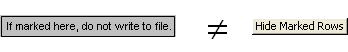
So "marking" a wire means that EZNEC doesn't know about it (it's not in the temporary model file), and "Hide Marked Rows" means that you don't have to see it either.
Finally, because all of the wires of this model have been "AutoSeg-ed" the segmentation density (20 segments per wavelength for all but wire 1) will automatically adjust as you change the dimensions and/or shape of the model, no matter how long or short you make any group of wires. In all the configurations below the total number of segments may change but each wire (except wire 1) will always have approximately 20 segments per wavelength. If you like you could even set both D and E to negative values and create a "funnel" vertical instead of a "top hat" vertical.
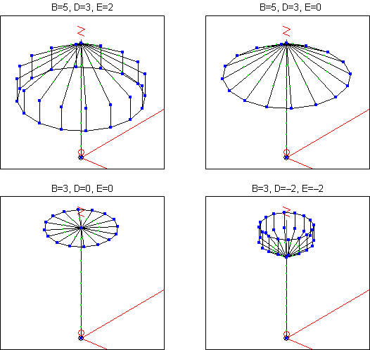
Okay, that last one is just silly. Time to move on.